DispPro 3000 - Software - Bungard Elektronik GmbH & Co.KG

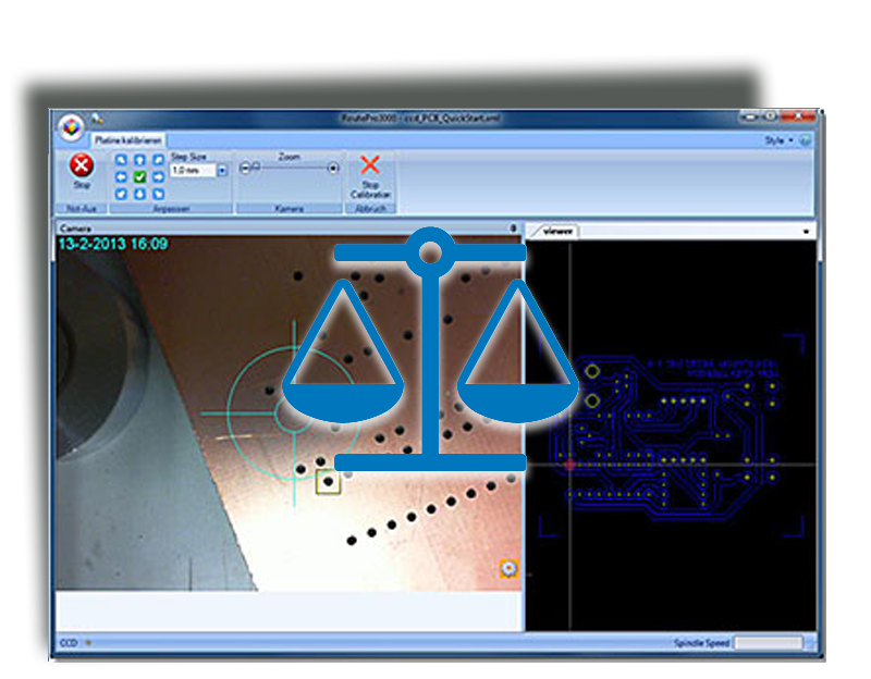
For all Bungard CCD machines

Calibrate 3000

With the calibration module, you can visually calibrate the position of your board. The software moves and rotates the board according to the actual position of the calibration marks or registration holes. For this purpose, the machine automatically drives to certain registration points on the layout and the user  centers the cross mark of the camera over the mark and acknowledges the position. Registration holes can be easily inserted e.g. with IsoCam. Height calibration is also possible with the help of standardized templates. The calibration function is useful if you e.g. do not want to work with reference pins for double-sided boards, or the board has been changed by other process steps (pressing multilayer, galvanic through hole plating), so the reference pins may lead to inaccuracies.
Another typical application is the rework, e.g. if after components assembly the circuit board can no longer be fixed with reference pins to the base.

Requirements:

  • a Bungard CCD
  • the Software RoutePro 3000
  • a calibration license Calibrate 3000
  • a camera (included in delivery)

Operation

To use the calibration functions, you need to mount the camera to the Bungard CCD and activate the calibration license. A possibly needed active usb-extension is not part of delivery. At first you must calibrate the offset between spindle tip and cross hair of the camera. Only if the camera offset to the spindle is correct you can start to calibrate the pcb. Fix your pcb to the base of the machine. Load the project into RoutePro 3000 and activate the calibration function in tab General.
If now you click on Start at tab Run CNC, the machine will at first move to the position, where it believes to find the drill hole on the utmost lower left (with a routing file the machine will drive to the start point of the vector on the utmost lower left. We recommend to use a drill layer, at best the reference hole file).
With the arrow buttons centre the cross hair on the actual position of the drill hole and confirm this position by clicking in the green check sign in the middle of the direction arrows. The camera will then drive to the drill hole on the upper right. After centering and confirming the position the software will move and rotate the layout in the viewer accordingly and processing of the board starts. The calibration remains active till the end of the process. Calibration will be lost if you open another project or if you change the position of the layout in the software (change of offset, scaling etc.)

Safety regulations

Pay heed to the safety regulations of the Bungard CCD

Techn. data

Application: machine calibration

Scope of delivery: Camera with USB cable, bracket for attachment to a CCD, also Inspect 3000 as a free bundle an active USB extension may be required. This is not included in the delivery.

Features: 720p HD video with auto focus. High precision lens with glass elements; Delivers sharp picture quality. TrueColor technology; Automatic exposure control for brilliant videos in powerful Colours. HD video recording at 720p; Draws up to 30 frames per second in true HD quality on. ClearFrame technology. Optimized for Windows 8; Quick setup, no driver installation required.

System requirements: Computer / operating system: Windows 8, Windows 7, Windows Vista, Windows XP with Service Pack 2 (SP2) or higher (except Windows XP 64-bit). At least: Intel Dual-Core 1.6 GHz or higher, 1 GB of RAM. Recommended: Intel Dual-Core 3.0 GHz or higher, 2 GB RAM

Hard disk: 1.5 GB of free space

Miscellaneous: USB 2.0

To use the calibration functions, you need to mount the camera to the Bungard CCD and activate the calibration license. A possibly needed active usb-extension is not part of delivery. At first you must calibrate the offset between spindle tip and cross hair of the camera. Only if the camera offset to the spindle is correct you can start to calibrate the pcb. Fix your pcb to the base of the machine. Load the project into RoutePro 3000 and activate the calibration function in tab General.
If now you click on Start at tab Run CNC, the machine will at first move to the position, where it believes to find the drill hole on the utmost lower left (with a routing file the machine will drive to the start point of the vector on the utmost lower left. We recommend to use a drill layer, at best the reference hole file).
With the arrow buttons centre the cross hair on the actual position of the drill hole and confirm this position by clicking in the green check sign in the middle of the direction arrows. The camera will then drive to the drill hole on the upper right. After centering and confirming the position the software will move and rotate the layout in the viewer accordingly and processing of the board starts. The calibration remains active till the end of the process. Calibration will be lost if you open another project or if you change the position of the layout in the software (change of offset, scaling etc.)

Modules for RoutePro 3000

Bungard Elektronik GmbH & Co.KG
fas fa-map-marker

Rilkestrasse 1
D-51570 Windeck

fa fa-fax

+49 2292 / 9 28 28 - 29